Trevi’s FO Flowsheet
Implementation
This flowsheet:
simulates the configuration of the pilot FO system that Trevi System constructed
incorporates the following unit models
one forward osmosis model from WaterTAP-REFLO
one mixer model from IDAES
two separator models from IDAES
two heat exchanger models from IDAES
three heater models from IDAES
supports steady-state only
is verified against the Trevi’s operational data and modeling results
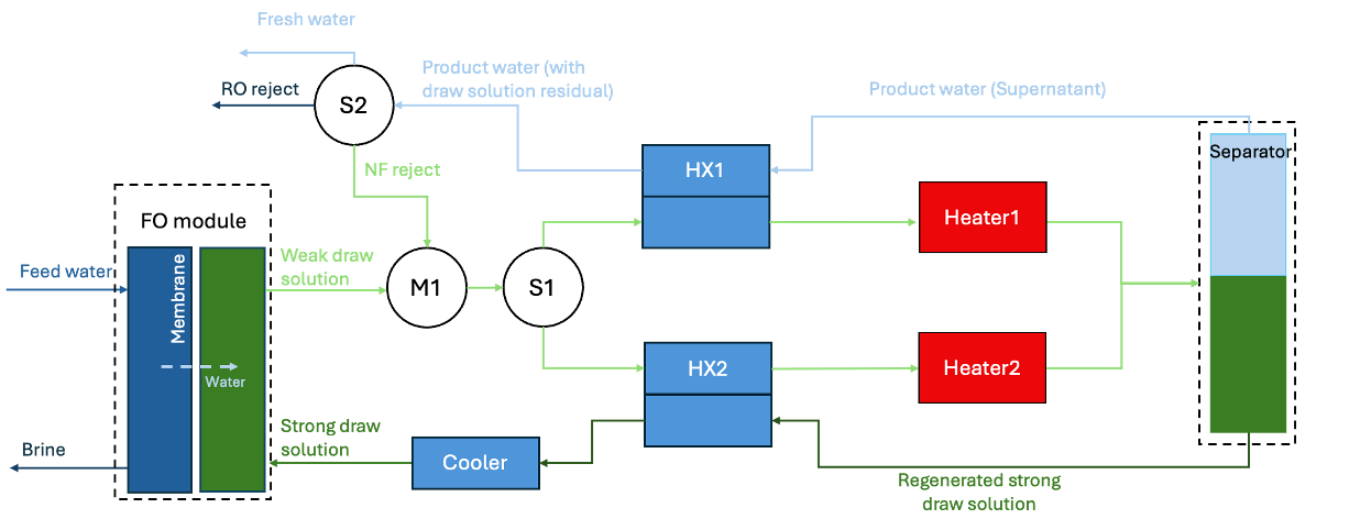
Figure 1. Diagram of Trevi Systems FO configuration
A discussion of each process component is given as following:
The FO membrane separates the feed seawater by the concentrated draw solution. Along the membranes, driven by the osmosis gradient, water from the feed side permeates the FO membrane and dilutes the draw solution on the draw solution side of the membrane.
FO brine exits the FO membrane module and is discharged after heat recovery in the heat exchanger and after chemical neutralization.
The diluted draw solution (approximately 40-50%) exits the membrane module and is circulated through the heat exchangers to the coalescer, where the draw solution polymer will be separated.
The draw solution is circulated in a loop between the coalescer and the FO membrane. In the coalescer the draw solution is separated, by means of the heat provided by the waste heat exchanger. Hot concentrated draw solution at 80 wt% draw solution polymer exits the coalescer and, after giving heat to the diluted draw solution from the FO module, enters the FO membrane module.
From the membrane module to the coalescer, the circulation loop of the diluted raw solution is as described above. During this circulation, the stream receives the brine generated by the final nanofiltration (NF) process.
In the coalescer the draw solution stream is separated into two components, (1) concentrated draw solution at 80 wt % draw solution polymer, and two (2) NF feed at < 1 wt% draw solution polymer.
Concentrated draw solution at 80 wt % draw solution polymer goes through the heat exchanger and enters permeate side of FO membrane module.
From the coalescer, the product stream is hot NF feed at ~ 1 wt % draw solution polymer, that after pre-heating the diluted draw solution as described above, is pumped to the low pressure NF unit by the NF feed pump.
An additional RO filtration step is installed for the NF permeate in case product water quality does not fullfil requirements, with special reference to rejection of Boron.
The NF brine stream, which is a warm stream containing the NF-rejected draw solution polymer, is recirculated and combined with cold dilute draw solution downstream of the FO membrane.
According to the efficiency of the heat exchangers, both the NF permeate and brine will be slightly warmer than the original feed seawater finally resulting in loss of heat.
Flowsheet Inputs
In addition to the input variables for the FO model, the following operational parameters should be specified:
Input Variables |
Variable name |
Symbol |
Units |
|---|---|---|---|
RO recovery ratio (if applied) |
|
\(RR_{RO}\) |
\(\text{dimensionless}\) |
Outlet temperature of weak draw from heat exchanger HX1 |
|
\(T_{HX1-cold-out}\) |
\(\text{°C}\) |
Outlet temperature of product water from heat exchanger HX1 |
|
\(T_{HX1-hot-out}\) |
\(\text{°C}\) |